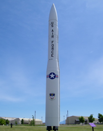

UHF Radio Receiver
UHF Radio Receiver
Click on the image for a larger view
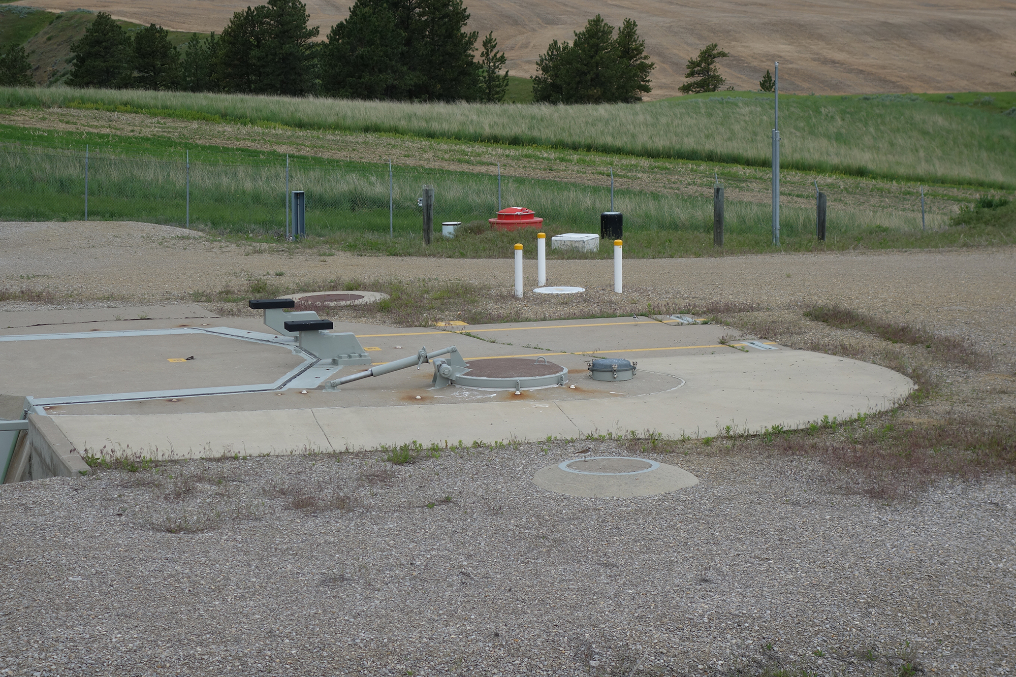
The Ultra High Frequency Radio Receiver (UHF) Antenna is pictured above, just above and slightly to the right of the Personnel Access Hatch. It has the three white poles surrounding it. It is a circular, semi conical hardened antenna, used to allow the Launch Facility to communicate with the Airborne Launch Control Center.
The former UHF Antenna is still in place, but is no longer operational. It is the circular concrete structure with the bird standing on it, just before the Personnel Access Hatch.
This is a feature designed into the Minuteman missile system that takes into account that if the Launch Control Center is no longer capable of sending a launch command to the Launch Facility, (if it has suffered from a catastrophic nuclear attack) the Airborne Launch Control Center can take over to complete that command to launch.
The Airborne Launch Control System, ALCS, is also referred to as the ALCC, Airborne Launch Control Center. The first generation of the ALCC was a modified Boeing C-135 Stratolifter cargo plane, with the title EC-135 "Looking Glass." The EC-135C carried sophisticated equipment that allowed the ALCC to connect remotely to the Launch Facility, through the UHF Radio Antenna at the LF.
The Air Force implemented this feature into the Minuteman force, with the foreknowledge of the distinct possibility that if and when the United States experienced a nuclear attack, a system needed to be available if and when a nuclear blast destroyed or disabled the Launch Control Center(s) (MAF,) preventing it from being able to send the command to launch.
For further information on the Airborne Launch Control System, follow the link below.
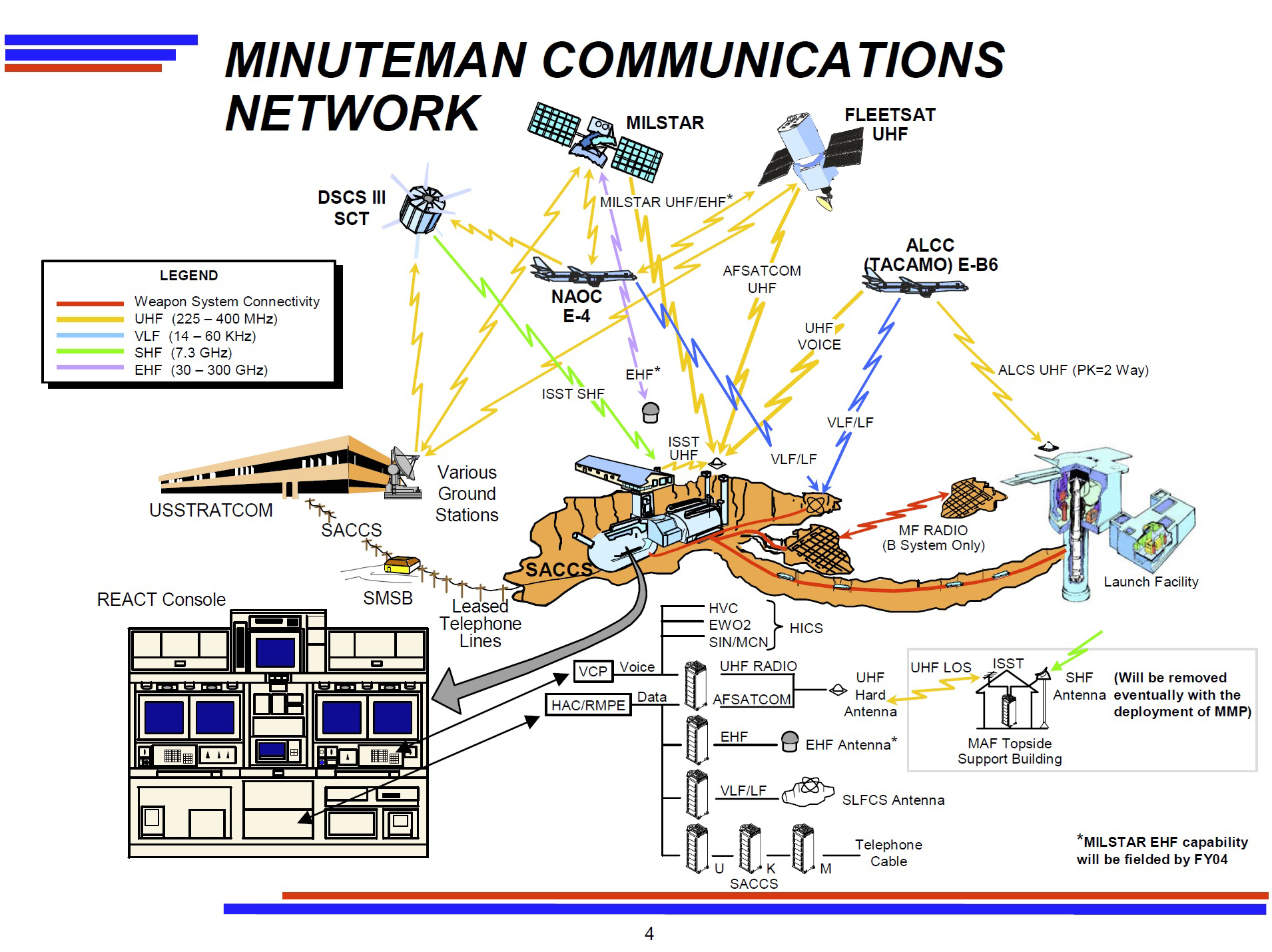
Minuteman Communications Network
Click on the image for a larger view
In order to gain a better understanding of how the Launch Facility communicates with the Launch Control Center, (also referred to as the Missile Alert Facility - MAF) as well as the various links of the entire network of communications within the Minuteman weapons system, a schematic outlining the network is included above.
Medium Frequency Antenna
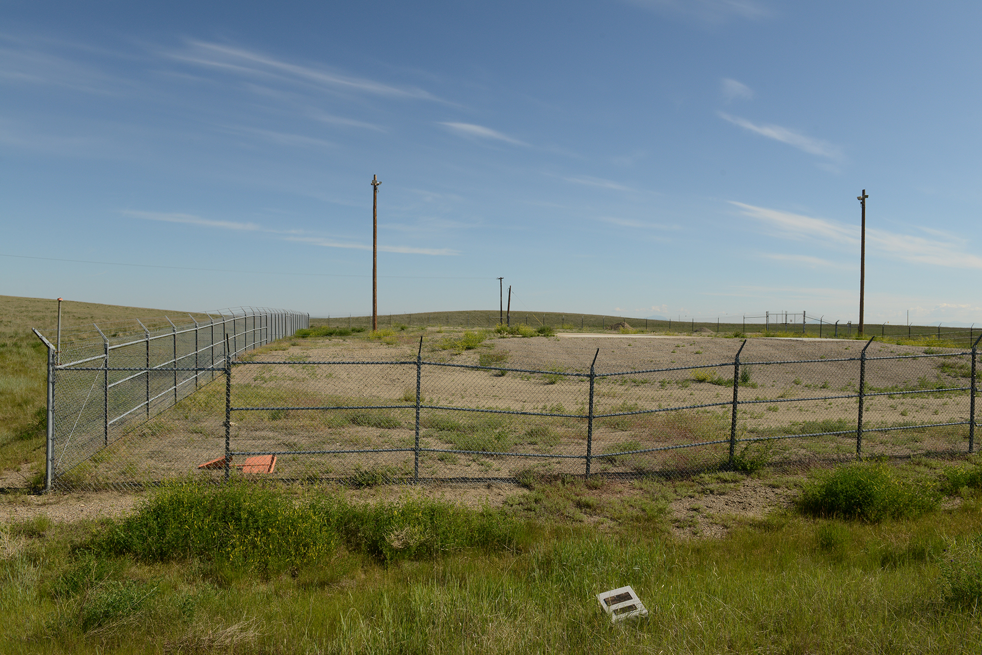
Sylvania Monument - Medium Frequency Antenna
Click on the image for a larger view
At the 564th Strategic Missile Squadron, located at Malmstrom Air Force Base in Montana, as well as Wing VI, located at Grand Forks Air Force Base in North Dakota, a second antenna was placed that provided the ability to send a command to launch by either sending the launch command through the HICS, Hardened Intersite Cable System, or through the Medium Frequency Antenna, the MF Antenna.
The image above shows a granite marker, or monument, that was placed just outside the Launch Facility, which marked where the Medium Frequency Antenna system entered into the LF. The granite marker can been toward the bottom, just to the right of the center of the photograph.
This photograph is of the recently deactivated P9 Launch Facility, located north of Conrad, Montana. This LF was formerly a part of the 564th SMS that was deactivated, starting in 2007. The LF had its Launcher Closure Door pulled off the Launch Tube and buried. Deactivation crews then filled the Launch Tube with dirt and gravel, and a few months before this photo was taken, the Air Force had a concrete cap placed over the Launch Tube and Launch Support Building.
Sylvania was the company who designed this system, and the brass plaques on the monument note the "Antenna AS-1660/F" system used at that site. Each plaque was marked with its unique serial number for each respective Launch Facility. The 5 Launch Control Facilities at the 564th SMS also had the granite marker with the brass Sylvania plaque placed at the LCF, which marked where the Medium Frequency Antenna entered into the Launch Control Facility. The MF antenna itself was buried outside the security perimeter fence at both the Launch Control Facility, as well as at each Launch Facility.
The interesting feature about the Medium Frequency Antenna was that the antenna was buried underground, both at the Launch Control Facility, as well as the Launch Facility. If the LCF had an issue with the HICS system, they could opt to send the launch command over the Medium Frequency Antennas. The 564th and Wing VI were the only squadrons to use the Sylvania system. This setup was sometimes referred to as the "Deuce system". Once the Air Force deactivated the entire VI squadron, it made the 50 missiles at the 564th obsolete, which carried very expensive maintenance costs for the 5 Missile Alert Facilities (LCF) and 50 Launch Facilities at the 564th SMS.
Medium Frequency Antenna - Launch Control Facility
Click on the image for a larger view
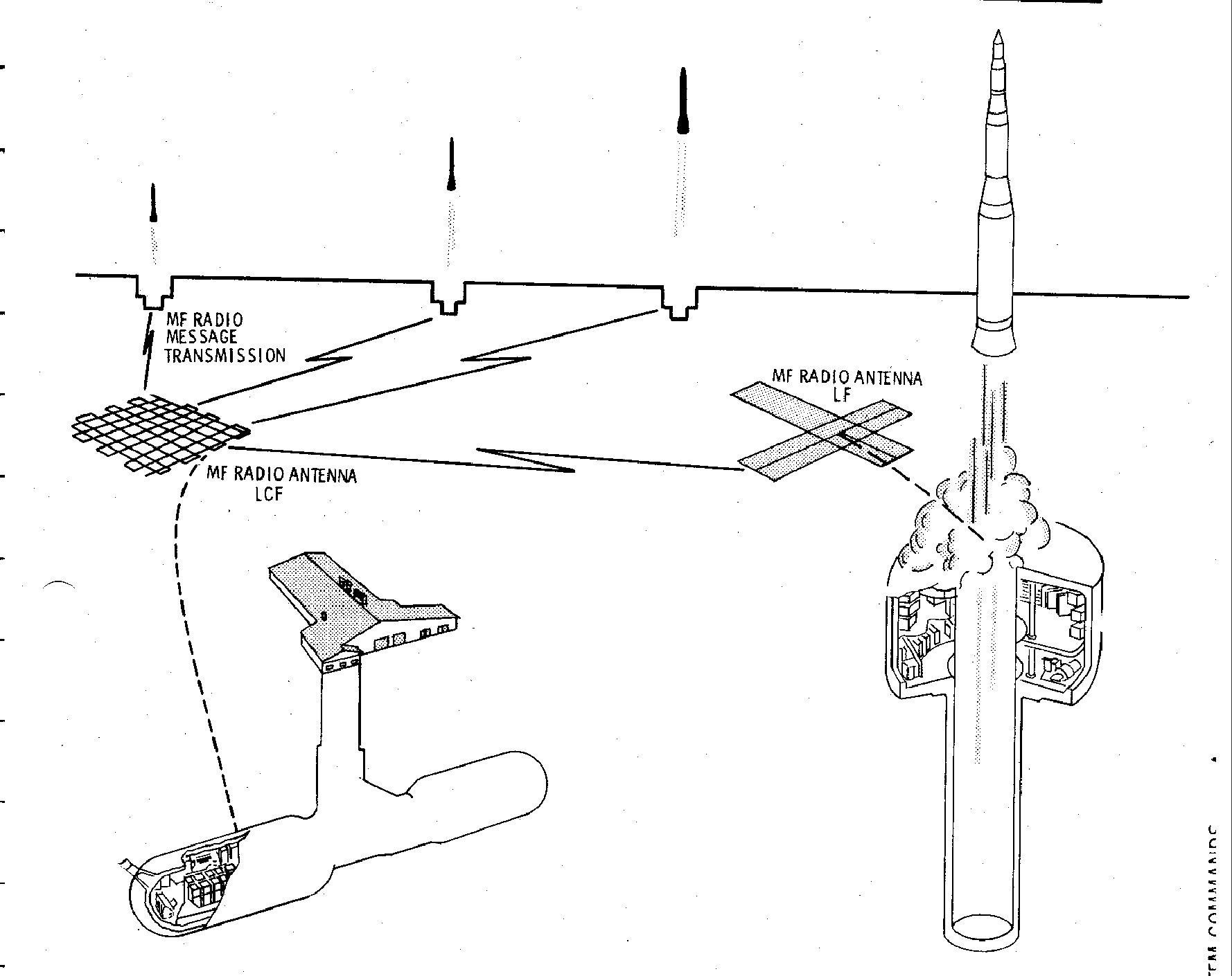
The image above provides a schematic of a visual representation of the layout of the Medium Frequency Antenna, located at both the Launch Control Facility, and the Launch Facility.
Medium Frequency Antenna - Launch Control Facility
Click on the image for a larger view
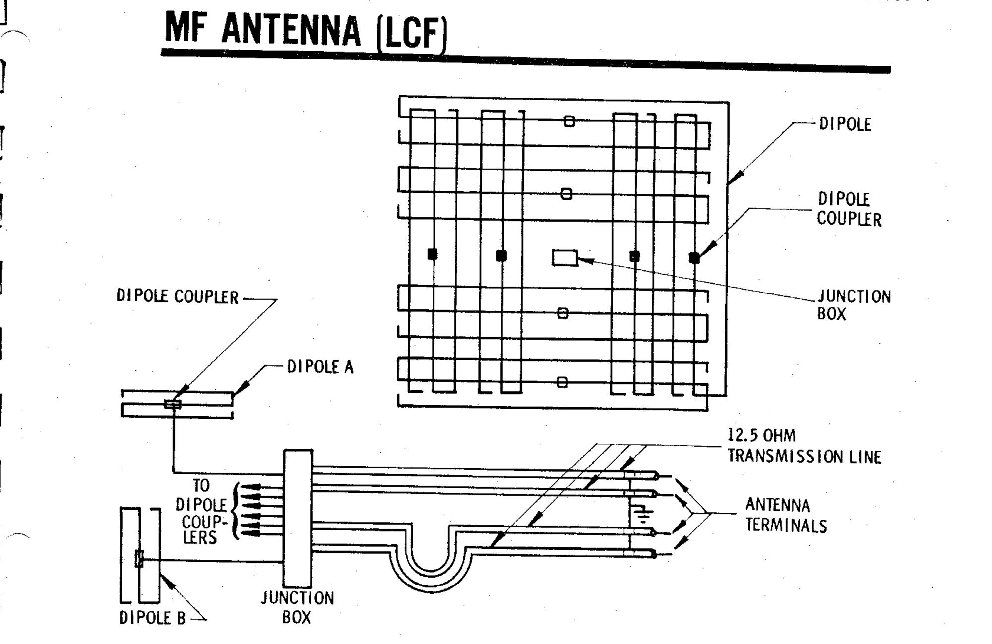
The image above provides a view of how the Medium Frequency Antenna is designed for the Launch Control Facility. This antenna is buried under the ground, outside the perimeter security fence of the LCF.
The MF Antenna installed at the LCF transmits and receives radio signals at a single frequency in the 415 to 490 kHz range. The antenna set consists of 8 insulated dipole antennas. Balanced, shielded transmission lines (100 ohms) couple the individual dipoles to the junction box. These 100 ohm lines are connected in parallel to a 25 ohm balanced, shielded transmission line (made up of two 12.5 ohm unbalanced lines) that runs from the junction box to the electrical surge arrester in the Launch Control Center capsule.
The antenna set has a minimum efficiency of -41.0 db compared to a short vertical monopole over a perfectly reflecting ground. This is achieved by the following configuration:
a) The antenna dipoles are placed in a quadrature arrangement;
b) An electrical phase difference of 90 degrees is provided between the two groups of four dipoles. This phasing is accomplished by having one of the 25 ohm transmission lines electrically longer than the other by one-quarter wavelength.
Medium Frequency Antenna - Launch Facility
Click on the image for a larger view
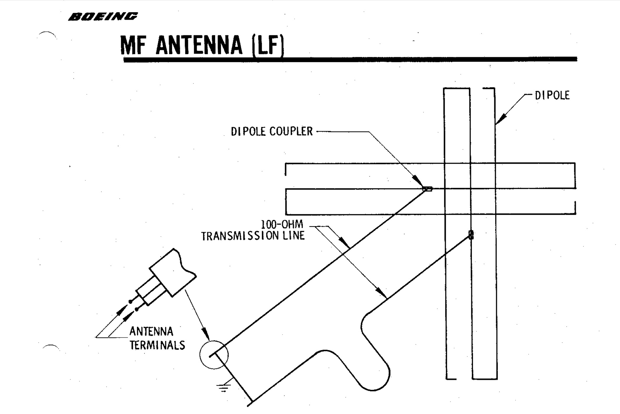
The image above provides a view of how the Medium Frequency Antenna is designed for the Launch Facility. This antenna is also buried under the ground, outside the perimeter security fence of the LF.
The MF Antenna installed at the LF transmits and receives radio signals at a single frequency in the 415 to 490 kHz range. The antenna set at the LF consists of 2 insulated dipole antennas. Balanced, shielded transmission lines (100 ohms) couple the individual dipoles to the electrical surge arrester in the Launch Tube.
The antenna set has a minimum efficiency of -44.9 db compared to a short vertical monopole over a perfectly reflecting ground. This is achieved by the following configuration:
a) The antenna dipoles are placed in a quadrature arrangement;
b) An electrical phase difference of 90 degrees is provided between the two groups of four dipoles. This phasing is accomplished by having one of the 2 transmission lines electrically longer than the other by one-quarter wavelength.